

 English
 русский
 Español
What Drawing Details Matter for Custom Metal Stamping Parts
A stamping project usually starts with a drawing, not a finished part. The drawing tells the manufacturer what shape is wanted, where the holes sit, which surfaces touch other components, and how the part will be used. When buyers plan Custom Metal Stamping Parts, the clarity of that drawing shapes quoting, tooling discussion, sampling, and inspection.
A vague drawing invites different readings. A designer may see a bend as a mounting edge, while a production engineer may see a forming risk. Settling these questions on paper costs far less than settling them after tooling work has begun.
Why Does Drawing Quality Matter Before Production?
A part can look simple on a screen and still need several forming steps. Bends, openings, raised ribs, and recessed areas all change how the sheet moves under the press. A clear drawing lets the manufacturer study these features before preparing the process.
Custom parts also differ from catalog items. They are usually built around one assembly, one housing, or one installation space, so a small misunderstanding can show up later as a bracket that does not line up with its mounting points.
| Drawing information | Why it matters |
|---|---|
| Overall shape | Shows the general form of the part |
| Feature locations | Relates holes and formed areas to one another |
| Material note | Identifies the intended metal |
| Surface requirements | Explains the expected appearance |
| Several views | Makes the structure easier to read |
| Revision label | Shows which design is current |
When the design changes during discussion, the revised drawing should reach everyone involved, not only the person who requested the change.
How Should Shape and Geometry Be Presented?
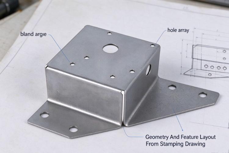
Overall geometry gives the manufacturer an initial sense of the part's shape and structure. A flat, washer-like component may need only one view, while a bracket with offsets and folded edges requires additional views to show its features clearly.
Each view has a job. The front view shows the outline, the side view explains bends and changes in depth, the top view shows how openings are arranged, a section view reveals internal shapes, and an isometric view gives a quick sense of the whole form. Views that repeat each other add clutter without adding clarity.
Geometry should also reflect real use. A mounting plate must meet other parts during assembly. A protective cover must follow the outline of the equipment it shields. A support bracket must connect to a larger frame through its formed sections.
Once the manufacturer understands the intended shape, the conversation can move to whether it suits stamping. A deep draw or a tight corner is easier to discuss at the drawing stage than after steel has been cut for tooling.
Which Material Details Belong on the Drawing?
Material affects both forming behavior and performance in service. The drawing, or the documents sent with it, should name the material the buyer wants.
This matters for Stainless Steel Stamping Parts in particular. Stainless is often chosen for appearance, corrosion resistance, or use in damp or hygienic settings, yet different grades form differently and should not be treated as interchangeable. A kitchen equipment bracket and a decorative panel may call for different grades, even though both are described as stainless.
Useful material notes include:
- The material type and grade
- The working environment, such as indoor, outdoor, or humid
- Contact with other components
- Appearance needs
- Material certificates, if required
- Whether the buyer or the manufacturer supplies the material
A general phrase such as "stainless steel" leaves room for guesswork. Naming the grade removes it.
How Do Bends, Holes, and Formed Features Affect Review?
Most stamped parts contain features that turn a flat sheet into something functional. Each feature influences forming, tool design, and how the part sits in its assembly.
Bends create mounting edges, stiffening sides, and connecting sections, so their direction and position should be unmistakable. Holes serve screws, alignment pins, wiring, or ventilation, and their position decides how the part installs. Raised, recessed, and embossed areas add strength or appearance but also change how material flows.
| Feature | Review focus |
|---|---|
| Bends | Direction and relation to nearby surfaces |
| Holes | Position and link to other components |
| Slots | Orientation and purpose |
| Raised areas | Shape and surrounding material |
| Recessed sections | Depth direction and nearby geometry |
| Edges | Shape and finishing needs |
Features rarely act alone. A hole placed close to a bend raises a different question from one in an open flat area, because the metal near the fold stretches during forming. The drawing should show these relationships clearly, and extra views are worth adding when the geometry is hard to read.
Why Do Tolerances and Fit Requirements Matter?
A stamped part seldom works alone. It may slide into a housing, clamp against another surface, or hold a component in position.
Tolerance information tells the manufacturer how much variation is acceptable. Not every dimension needs the same attention. Some control how parts assemble, while others only describe general shape. Marking the important dimensions helps the production team focus inspection where it counts.
Before production, buyer and manufacturer can walk through a short checklist:
- Which surfaces contact other components
- Which openings are used for assembly
- Which features control alignment
- Which dimensions affect movement or clearance
- Which areas relate mainly to appearance
Agreeing on these points early prevents arguments during inspection, since both sides know what the finished part is expected to do.
What Surface and Edge Requirements Should Be Shown?
Surface condition affects appearance and use. A visible decorative panel carries different expectations from an internal bracket that no one sees after assembly. Parts used near moisture or chemicals may need protection suited to those conditions.
Edges need equal attention. Stamping can leave burrs or sharp corners, and depending on the design, further finishing may be needed. A part handled by workers on an assembly line should not cut hands, and a part that slides into a slot should not catch on a rough edge.
Points worth discussing include:
- Whether visible faces need a consistent look
- Which areas need surface treatment
- Whether coatings are part of the order
- How edges should be finished
- Which surfaces must stay free from marks
These details apply strongly to Stainless Steel Stamping Parts, where the look of the metal itself is often part of the product design. A written surface specification also gives inspectors something concrete to check instead of leaving appearance to personal opinion.
How Should Revisions Be Managed?
Custom projects often change along the way. A buyer may move a mounting hole, adjust a bend, switch the material, or alter how the part meets its neighbor.
When several versions of one drawing circulate, the production team cannot tell which one is current. Quotes, samples, and tooling talks may then refer to different designs.
| Revision detail | Purpose |
|---|---|
| Drawing number | Separates one part from another |
| Revision label | Shows the version under review |
| Change description | Explains what was updated |
| Approval status | Shows readiness for the next stage |
| Supporting notes | Gives context for unusual changes |
Send revised drawings through an agreed channel, and ask the manufacturer to confirm receipt. A change is not just a file swap. Even a small move of a hole can affect forming order, tooling, and inspection. Reviewing changes together exposes production effects before they become costly.
What Should Buyers Prepare Before Sending a Drawing?
A useful package gives enough information to understand the part without burying key points in detail. Buyers can gather:
- The current drawing with clear views
- Material and grade requirements
- Fit and assembly information
- Surface and edge expectations
- The intended application
- Revision data
- Reference samples or related assembly drawings, if available
The application deserves a short explanation. Knowing whether a part supports, protects, connects, or decorates helps the manufacturer spot issues that the drawing does not show. A note on how the part sits among neighboring components can reveal clearance or access problems early.
The manufacturer then checks whether the information is complete and consistent, and raises questions before a production plan is written. A clear package gives designers, buyers, and production staff the same reference when discussing shape, material, features, fit, and inspection for Custom Metal Stamping Parts.

 Yongkang Ruizan Industry and Trade Co., Ltd.
A company specializing in metal stamping and mold design and manufacturing.


- Phone: +86-18072455799
- Email: [email protected]
- Address: No. 23, Qilong Road, Natural Village, Zhiying Town, Yongkang City, Jinhua City, Zhejiang Province, China
Copyright © Yongkang Ruizan Industry and Trade Co., Ltd. All Rights Reserved.

Custom Stamping Sheet Metal Hardware Machining Factory