

 English
 русский
 Español
What Role Does Tolerance Control Play in Metal Stamping Parts
Metal stamping parts can look genuinely simple when viewed as individual components, but their actual value often depends on how well they fit into the larger assembly they're headed toward. A small difference in a hole position, edge location, bend position, or overall shape can affect how another component sits against it on the line.
This makes tolerance control a genuinely important part of metal stamping production. The purpose isn't simply making every part look identical to the last one. It's keeping important dimensions within an agreed range, so parts can get assembled, inspected, stored, and used with fewer unexpected problems down the road.
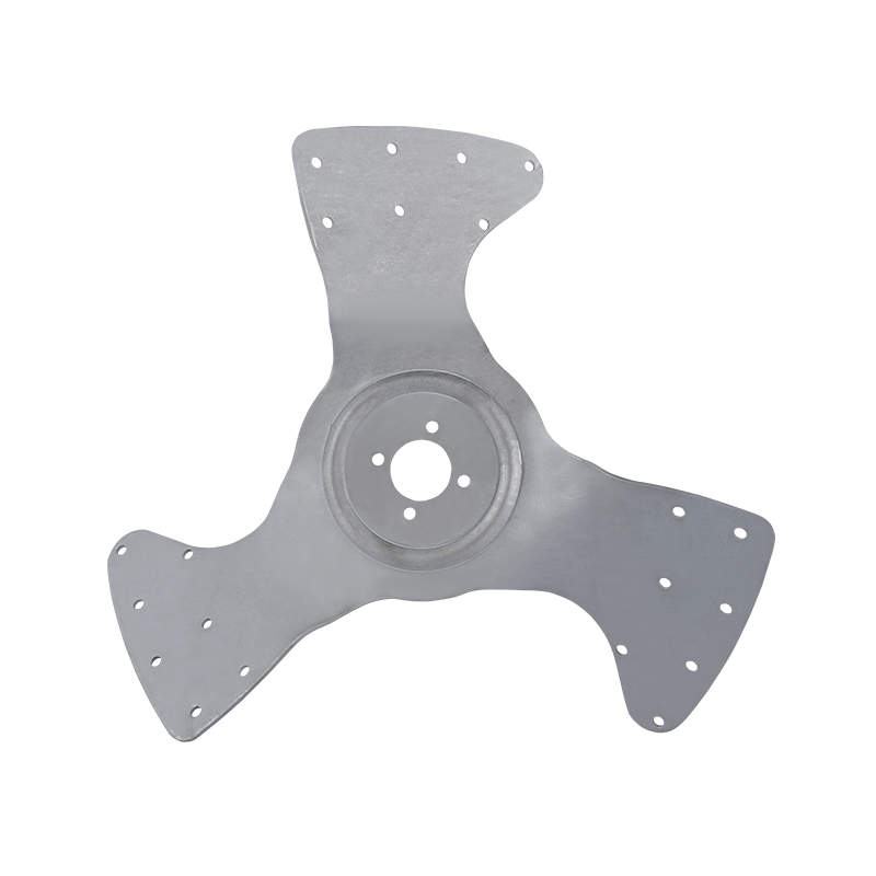
For engineering teams and B2B buyers, tolerance control also provides a practical way to connect drawings with real production on the floor. Custom Metal Stamping Parts may have genuinely different dimensional requirements from one project to another, while Stainless Steel Stamping Parts can also require careful control when they're used as fitted components.
Why Does Tolerance Control Matter in Metal Stamping Parts?
Every manufactured part has some variation built into it. Production conditions, equipment, tooling condition, material behavior, and measurement methods can all affect the final result coming off the press.
Tolerance control defines which variations are acceptable for a specific feature on the part. It helps manufacturers understanding which dimensions need closer attention and which areas can allow more natural variation without causing problems.
| Part Feature | Why Tolerance May Matter |
|---|---|
| Hole position | Affects connection with another component |
| Outer edge | Influences fit inside a housing |
| Bend location | Changes the position of connected surfaces |
| Opening shape | Can affect insertion or movement |
| Overall dimensions | Influence assembly clearance |
Without clear tolerance requirements, different people may interpret the same drawing in genuinely different ways. This can create confusion between engineering, production, inspection, and purchasing teams working from the same file.
A clear tolerance approach gives these groups a shared reference point to work from.
How Do Dimensional Tolerances Affect Assembly Fit?
Assembly fit is one of the clearest reasons controlling dimensions matters at all. A stamped part may need sitting inside another component, connecting with a fastener, or aligning with a neighboring part on the assembly line.
If a feature is too large, too small, or positioned differently from the intended location, assembly may become genuinely difficult for the worker on the floor. A part may need additional adjustment, or two components may not sit together as planned in the drawing.
Tolerance control therefore needs considering the relationship between mating parts, rather than each dimension in isolation.
For example, a hole shouldn't get reviewed only as a hole on its own. Its position, size, surrounding material, and relationship with the component that enters or connects to it all matter together.
The same principle applies to edges and bends throughout the part. A bend can change the position of a surface, which may then affect the clearance between two assembled components down the line.
What Is the Relationship Between Tolerance and Assembly Clearance?
Assembly clearance refers to the space allowed between parts that need to fit together or move relative to each other during operation. Too little clearance can make assembly genuinely difficult, while excessive clearance may affect the intended position of the components once installed.
Tolerance and clearance are therefore closely connected in practice.
A design team may need considering several dimensions together, rather than checking each one independently of the others.
| Assembly Area | Tolerance Consideration |
|---|---|
| Sliding connection | Space between moving surfaces |
| Inserted component | Opening and component size |
| Fastened joint | Hole position and matching features |
| Housing fit | Outer dimensions and internal space |
| Cover or panel | Edge position and surrounding clearance |
A part can meet an individual dimensional requirement and still create an assembly problem when several variations combine on the same piece. This is why tolerance planning should consider the complete relationship between connected components, rather than one feature at a time.
How Can Tolerance Accumulation Affect an Assembly?
When several dimensions contribute to the same assembly position, their variations can genuinely combine on the finished part. This is sometimes referred to as tolerance accumulation across a chain of features.
A simple example can involve several stamped sections positioned along the same assembly path. Each individual feature may remain within its allowed range on its own, but the combined variation can shift the final position noticeably.
This creates a genuinely practical challenge for engineers reviewing the drawing.
Instead of checking a single dimension, it can be useful to examine the complete chain of related features together. A practical review can identify the dimensions that affect the final position, then check how each feature relates to the next component in the chain. Considering the allowed variation across the connected parts can follow, along with determining which dimensions have the greatest effect on assembly. Defining inspection points around these relationships can complete the process.
This approach can help preventing a situation where every individual feature appears acceptable, but the finished assembly becomes genuinely difficult to fit together.
How Does Batch Consistency Relate to Tolerance Control?
Tolerance control isn't only about one part sitting on a bench. It also matters when the same stamped component gets produced repeatedly across a production run.
B2B buyers often need parts from different production batches remaining compatible with the same assembly months later. If the dimensions shift noticeably between batches, an assembly process may become genuinely less predictable for the team downstream.
Batch consistency depends on how well production conditions get controlled and how clearly important dimensions get defined from the start.
Manufacturers can monitor areas such as feature position, opening size, and bend location across a run. Part profile, surface alignment, and overall shape matter too as the batch progresses.
The purpose isn't eliminating every natural difference between parts. Instead, production should remain within the dimensional range agreed for the part throughout the run. This distinction proves useful because practical manufacturing always involves some variation from piece to piece.
Why Are Critical Dimensions Different From General Dimensions?
Not every dimension has the same effect on a finished product once it's assembled. Some dimensions directly affect assembly, movement, or connection with another part. Others mainly describe the general shape of the part and may have genuinely more flexibility built in.
Separating these features can make tolerance planning genuinely easier for the engineering team.
| Dimension Type | Typical Importance |
|---|---|
| Assembly-related feature | Directly affects component fit |
| Connection feature | Affects joining or fastening |
| Position feature | Influences alignment |
| Clearance feature | Affects available space |
| General profile | Describes overall part shape |
This doesn't mean general dimensions can get ignored entirely. It means engineering and inspection teams can pay particular attention to dimensions that have a direct relationship with assembly performance on the line.
For Custom Metal Stamping Parts, this distinction can prove especially useful because each project may involve a genuinely different combination of fitted and non-fitted features.
How Does Hole Position Affect Stamped Part Assembly?
Holes often get used connecting stamped parts with other components down the assembly chain. Their position can therefore prove genuinely more important than their appearance alone on inspection.
A hole may have the correct general shape but still cause an assembly problem if its center position shifts relative to another feature nearby. This is why inspection may need considering the relationship between the hole and surrounding edges, bends, or other holes on the same part.
For repeated parts, consistent hole placement can also make assembly genuinely more predictable across a production run. The same principle applies to multiple-hole patterns on a single piece. When several holes work together, their relative positions can matter genuinely as much as their individual dimensions checked separately.
How Can Bend Tolerance Influence Part Position?
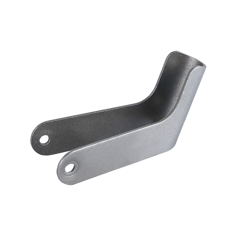
A bend changes the shape of a stamped part and can move one section relative to another along the piece. This makes bend position genuinely relevant to assemblies where several surfaces need meeting at a specific point.
If the bend occurs at a genuinely different location than intended, the final section may sit too close to another component or leave more space than expected in the housing. Bend tolerance can therefore affect panel alignment, mounting position, and surface contact throughout the assembly. Assembly clearance and connection location depend on it too.
The effect can become genuinely more noticeable when several bends sit present on the same component. Manufacturers need considering the relationship between the flat section, bend location, and finished shape, rather than reviewing each feature separately on its own.
Why Is Inspection Planning Important for Metal Stamping Parts?
Inspection should reflect how the part will actually get used once it leaves the shop. Measuring every possible feature in the same way may create unnecessary work without providing genuinely useful information back to the team.
A genuinely more practical approach identifies the dimensions that influence assembly and product function specifically. Inspection plans can start by reviewing the drawing requirements, then identifying assembly-related features that matter most. Selecting suitable measurement methods comes next, followed by checking representative parts during production runs. Recording dimensional results and reviewing changes when production conditions shift rounds out the cycle.
The inspection method should also match the feature being checked at that moment. A hole position, flat edge, bend location, and overall profile may require genuinely different ways of measurement depending on the geometry involved. Clear inspection planning helps connect manufacturing requirements with actual production checks happening on the floor.
How Does Measurement Method Affect Tolerance Evaluation?
A tolerance is only useful when the related feature can get measured in a genuinely consistent way across inspectors. Different measurement approaches can produce different readings if the part gets positioned differently or if the measurement reference stays unclear.
This makes the measurement method genuinely part of the quality process itself. For example, a flat component may need placing against a defined reference surface before certain dimensions get checked. A formed component may need a genuinely different reference because its final shape is no longer flat after forming.
Manufacturers and buyers can therefore discuss the measurement reference and inspection location together. Feature definition, measurement method, and recording method matter too in that conversation. Clear communication in these areas can reduce disagreements between supplier and buyer down the line.
What Inspection Requirements Should Buyers Define?
Buyers can help improving tolerance control by providing clear inspection expectations before production begins on the order. The requirements should focus on dimensions that affect the intended use, rather than creating unnecessary inspection conditions that slow things down.
Useful information may include the drawing, critical feature locations, and assembly relationships between parts. Inspection method and acceptable dimensional ranges round out the package. For B2B purchasing, the inspection discussion can also cover how production batches will get checked and how inspection records will get handled between the two sides.
A clear agreement can help both sides understanding what constitutes an acceptable part before the run starts. This proves particularly relevant when stamped components become part of a larger assembly supplied to different production locations across a supply chain.
How Do Stainless Steel Stamping Parts Require Consistent Dimensional Control?
Stainless Steel Stamping Parts may get used in assemblies where dimensional consistency matters across repeated production runs over time. The focus should remain on the finished geometry, rather than assuming the material name alone determines the required tolerance.
The stamped shape, feature location, forming sequence, and inspection method can all influence the finished dimensions produced during manufacturing. Manufacturers can therefore review the relationship between material behavior and final part shape during production planning, before any piece is stamped.
For buyers, it proves useful communicating which features control assembly fit specifically. This allows the supplier understanding where dimensional consistency matters and where normal production variation may prove acceptable instead.
How Can Manufacturers Control Tolerances Across Production Batches?
Batch control requires attention throughout production, rather than relying only on final inspection at the end of the run. Equipment condition, tooling condition, material handling, setup, and inspection practices can all influence dimensional consistency across a batch.
Manufacturers can establish regular checks around important features and compare results against the agreed requirements as the run progresses. When a change appears, production teams can review whether the issue comes from setup, tooling, material behavior, or another part of the process entirely.
This approach allows tolerance control becoming part of routine production management, rather than an afterthought. It also gives buyers a genuinely clearer basis for discussing batch-to-batch consistency with suppliers over the life of a contract.
What Role Does Tooling Condition Play in Dimensional Consistency?
Tooling influences how the sheet material gets formed into the intended shape on each stroke of the press. Changes in tooling condition can therefore affect feature position, edge condition, or formed geometry over the life of the tool.
This doesn't mean every dimensional change comes from tooling alone. Material condition, equipment setup, handling, and other production factors can also contribute to a shift observed on the floor.
A useful production process therefore connects tooling checks with dimensional inspection throughout the run. If repeated inspection shows a gradual change in an important feature, manufacturers can review the production setup before the variation affects a larger batch downstream.
This type of monitoring can support genuinely more stable production without adding unnecessary complexity to the manufacturing process itself.
How Can Tolerance Control Support Custom Metal Stamping Parts?
Custom Metal Stamping Parts often need fitting a specific assembly, which makes tolerance planning part of the design discussion from day one. The buyer and manufacturer can review which features need close control and which dimensions can allow genuinely more flexibility instead.
This helps avoiding applying the same tolerance approach to every feature on the part regardless of function. A custom component may contain several holes, bends, openings, and contact surfaces. Their relationships should get considered together when defining inspection requirements for the project.
| Feature | Procurement Discussion |
|---|---|
| Mounting hole | Position relative to assembly |
| Formed section | Final position after forming |
| Outer edge | Relationship with housing |
| Opening | Clearance for connected component |
| Contact surface | Position within assembly |
Clear communication can also help suppliers understanding why a particular dimension matters to the end use. This makes technical discussions genuinely more focused and can reduce unnecessary revisions during production later on.
How Should Buyers Discuss Tolerance With Suppliers?
Tolerance discussions become genuinely easier when they're connected to actual assembly needs, rather than an abstract spec. Instead of simply asking whether a supplier can make a part, buyers can explain how the part will get installed, which features connect with other components, and where clearance genuinely matters.
A useful discussion can cover drawing interpretation and critical dimensions, then move to assembly clearance and inspection references. Batch consistency and inspection records can form the middle of the discussion, followed by production change control toward the end.
This gives both sides a genuinely clearer understanding of the expected part condition before the order gets placed. It also helps procurement teams compare suppliers according to actual production requirements, rather than general claims about capability found in a brochure.
How Can Tolerance Control Improve Communication Between Engineering and Purchasing?
Engineering teams often focus on fit and function, while purchasing teams may focus on production feasibility, inspection, cost, and supply consistency instead. Tolerance control provides a genuinely common point of discussion between these two groups.
When a drawing clearly identifies important dimensions and their relationships, purchasing teams can communicate those requirements genuinely more accurately to suppliers on the other end. Suppliers can then review whether the requested tolerance matches their production and inspection processes already in place.
This reduces the chance of important requirements getting lost between design, purchasing, manufacturing, and inspection along the chain. For ongoing B2B projects, clear dimensional communication can also make repeat orders genuinely easier to manage because the same expectations can get referenced during later production runs.
What Should Be Checked Before Approving a Stamped Part?
Before approving a production part, buyers and engineering teams can review whether the dimensions that affect assembly stay within the agreed requirements set earlier. The inspection shouldn't focus only on visual appearance of the piece.
Useful checks can include key hole locations and important openings across the part. Bend positions and assembly surfaces matter too, along with overall part shape and clearance-related features. Batch consistency rounds out the list of things worth reviewing.
The results should be considered alongside the intended assembly for the part. A dimension that appears acceptable on its own may still require attention if it changes the relationship between two connected components further along the process. This is why tolerance control works better when dimensional inspection and assembly requirements are discussed together rather than treated as separate concerns.

 Yongkang Ruizan Industry and Trade Co., Ltd.
A company specializing in metal stamping and mold design and manufacturing.


- Phone: +86-18072455799
- Email: [email protected]
- Address: No. 23, Qilong Road, Natural Village, Zhiying Town, Yongkang City, Jinhua City, Zhejiang Province, China
Copyright © Yongkang Ruizan Industry and Trade Co., Ltd. All Rights Reserved.

Custom Stamping Sheet Metal Hardware Machining Factory