

 English
 русский
 Español
How Do CNC Stainless Steel Parts Take Shape
Stainless steel is often selected for parts that need to remain usable around moisture, repeated handling, or regular contact with other components. A stainless steel block, plate, or bar does not look much like a finished component when machining begins. Its final shape comes from removing material from selected areas while keeping other areas in place.
Machining behavior depends on the grade and condition of the material. Stainless steel can resist cutting more than some common metals, and heat can build around the cutting area during an extended operation. Tool condition, workpiece support, and cutting movement therefore need to match the material rather than follow a single setting for every part.
Part design also changes the way the material should be processed. A simple mounting plate may need several holes and edge cuts, while a mechanical component can contain steps, recesses, curved sections, and contact surfaces. Each feature takes space away from the original blank, so the machining route needs to leave enough material where later operations still have to take place.
For CNC Stainless Steel Parts, material preparation is also worth checking before cutting starts. The blank should have enough allowance for the required shape, while its surfaces need to provide a reliable basis for holding and positioning. Poor preparation can make later machining harder even when the cutting process itself is properly arranged.
How Does CNC Machining Shape Stainless Steel Components?
CNC machining does not form a stainless steel component in one single cut. Material is removed in stages, with each stage dealing with a particular part of the shape.
Cutting may start around the outside to establish the general profile, followed by operations for holes, slots, recessed areas, or other features. Areas that require a cleaner surface or closer dimensional control can receive additional finishing passes.
Machining order matters because removing material changes how the workpiece is supported. A thick section may provide useful rigidity during an early operation. Once a large amount of material has been removed, that same section may become thinner and require different support.
A practical sequence often looks like this:
- Prepare a suitable stainless steel blank
- Secure the workpiece against movement
- Establish the main outside shape
- Machine holes, grooves, steps, or recesses
- Refine important surfaces
- Check dimensions and visible surface condition
For a component with several features, the cutting path needs to make sense as a whole. Moving repeatedly between unrelated areas can add unnecessary handling, while machining a feature too early may make later positioning more difficult.
Tool access is another everyday concern. A narrow groove may not leave enough room for a large cutting tool. A deep pocket can also make it harder for the tool to reach the bottom while maintaining stable cutting. Looking at the finished shape from a manufacturing perspective helps reveal such problems before material is removed.
How Does Component Geometry Affect CNC Stainless Steel Parts?
A drawing may show a finished component as a single object, although machining treats it as a collection of surfaces and features. Outer edges, holes, steps, grooves, flat areas, and curved sections each place different demands on the cutting process.
Consider a part with several mounting holes. Hole position is not only a matter of making openings in the material. Each opening needs to sit in the correct relationship with the outside edges and nearby surfaces so that another component can later be attached.
A stepped surface creates a similar relationship. Its height affects the space available for another part, while its edge may serve as a contact area. Removing slightly too much material from a functional surface can therefore change how the finished component fits.
Curved areas bring tool access into the picture. A tool needs enough room to reach the intended surface without colliding with surrounding sections. Narrow corners and deep recesses may also require changes in the machining route.
When reviewing a stainless steel component, the geometry can be considered through several practical areas:
- Outer profile: Controls the basic shape and available space.
- Mounting features: Connect the component with other parts.
- Contact surfaces: Provide areas for fitting, sliding, or support.
- Recessed features: Remove material while retaining surrounding sections.
Such a review helps connect the drawing with the actual machining process. For CNC Stainless Steel Parts, dimensions rarely work in isolation. The location of one hole may depend on an edge, while a groove may need to remain at a certain distance from a mounting surface.

What Role Does Workpiece Positioning Play in Stainless Steel Machining?
A stainless steel workpiece needs to stay in a known position while cutting takes place. Clamping holds the material, while locating surfaces help establish its relationship with the machine.
Positioning becomes more noticeable when several faces of one component need machining. After one face has been processed, the workpiece may need to be turned or repositioned. A new position still needs to relate correctly to the surfaces already produced.
| Positioning Point | Practical Check | Why It Matters |
| Workpiece support | Check for movement during cutting | Helps keep the shape stable |
| Locating surface | Use a clear reference area | Keeps features related to the intended position |
| Clamping area | Avoid blocking machining surfaces | Leaves enough access for cutting |
| Repositioning | Keep the same orientation logic | Helps different faces remain related |
Support becomes especially important as more material is removed. A blank that feels rigid at the beginning may become less supported after a large section has been cut away. The holding method may therefore need to account for the component's shape at different stages rather than only its original form.
Good positioning is not simply about tightening a fixture. Contact areas, cutting direction, remaining material, and later operations all need to fit together. When those details are considered during process planning, the transition from one machining stage to another becomes easier to control.
How Are CNC Stainless Steel Parts Checked After Machining?
Machining does not end when the cutting process stops. A finished stainless steel component still needs to be checked against its intended shape. Inspection usually starts with the features that affect fitting or assembly, followed by general dimensions and visible surface condition.
Hole position is one practical point to check. A hole can have the expected diameter while still being placed incorrectly relative to an edge or another hole. For components used with other mechanical parts, the relationship between features can matter as much as an individual measurement.
Flat surfaces also need attention. A surface that looks smooth may still have unwanted marks, uneven edges, or small burrs left from cutting. Edge condition can affect assembly, handling, and contact with another component.
Inspection can be arranged around several areas:
- Overall external shape
- Hole location and opening condition
- Groove and recessed areas
- Contact and mounting surfaces
- Edge condition and visible machining marks
Checking during production can also help prevent repeated problems. A change in tool condition may gradually affect a surface, while a positioning problem can influence several related features. Early inspection gives the machining process a chance to be adjusted before the same issue continues through later operations.
How Do CNC Stainless Steel Parts Differ From Stainless Steel Stamping Parts?
CNC machining and stamping can both produce stainless steel components, although the way material is shaped differs considerably. CNC machining removes selected material from a solid blank, while stamping uses forming tools to press sheet material into a required shape.
For CNC Stainless Steel Parts, the starting material can take the form of a block, bar, plate, or another suitable blank. Cutting then creates the required geometry. Such a process is useful when a component contains different depths, isolated holes, recesses, or shapes that cannot be formed simply by pressing a flat sheet.
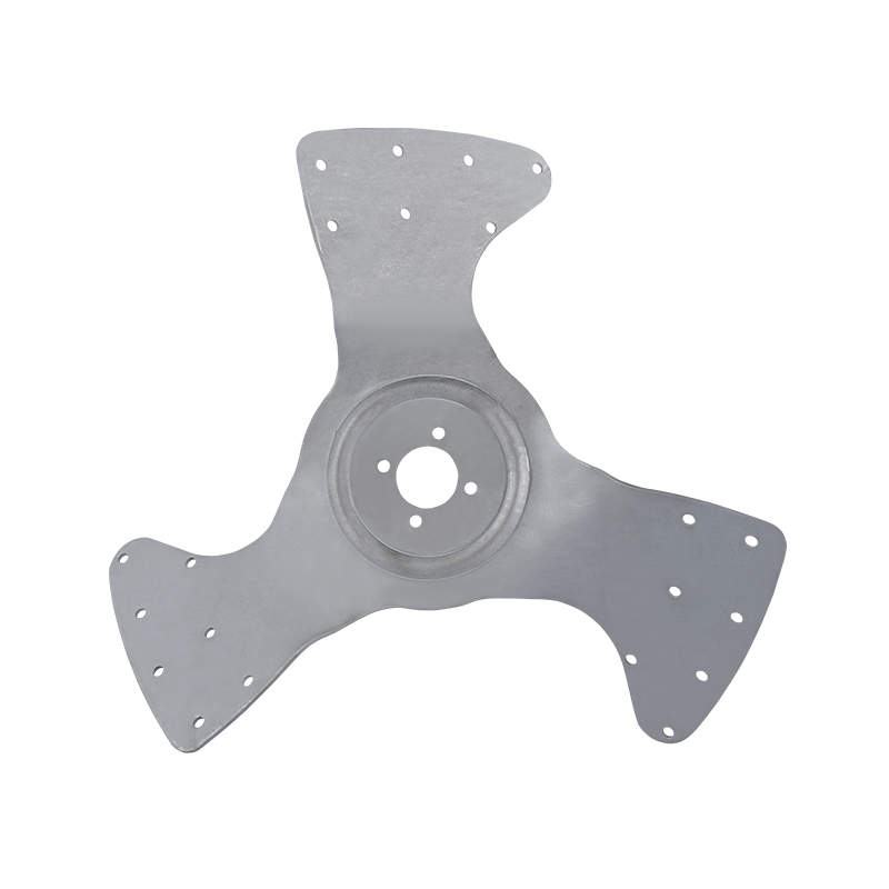
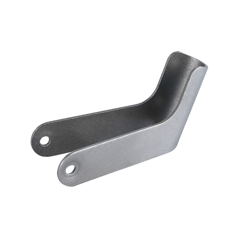
Stainless Steel Stamping Parts normally begin with sheet material. A stamping tool applies controlled force to cut, bend, or form the sheet. Part geometry therefore needs to suit the movement of the material during forming.
| Manufacturing Approach | Starting Material | Typical Shape Consideration | Process Character |
| CNC machining | Solid block, bar, or plate | Various surfaces, holes, steps, and recesses | Material is removed in stages |
| Stainless steel stamping | Sheet material | Flat sections, bends, openings, and formed areas | Material is cut or shaped with forming tools |
Choice of process depends on the component rather than a simple preference for one method. A part with a thick body and several machined surfaces may fit a cutting process naturally. A sheet component with repeated bends may be more suited to stamping.
Production quantity can also influence process planning, although geometry, material condition, tooling requirements, and dimensional needs still need consideration. CNC machining can accommodate changes in component geometry through revised machining paths, while stamping relies more heavily on the suitability of the forming tool for the intended shape.
How Does Design Influence the Final Stainless Steel Component?
A component can be easy to describe on a drawing and still present practical difficulties during machining. Design details such as narrow grooves, deep recesses, thin walls, sharp internal corners, and closely positioned holes can affect tool access and workpiece support.
Internal corners provide a simple example. A rotating cutting tool naturally has a rounded cutting path, so a very sharp internal corner may require a special approach or a design adjustment. Similar issues can appear around narrow slots where the available working space is limited.
Wall thickness also deserves attention. Removing material from both sides of a thin section can reduce its rigidity during later operations. Support becomes harder to maintain as the remaining material becomes smaller, making the machining sequence an important part of design planning.
A practical design review can ask:
- Can the required surface be reached by a suitable cutting tool?
- Is enough material available for positioning and clamping?
- Can important surfaces remain supported during machining?
- Are holes and grooves placed with enough surrounding material?
- Can the required shape be produced without unnecessary operations?
Such questions connect product design with actual workshop conditions. A component does not need to be redesigned simply because machining requires several operations. The useful goal is a reasonable relationship between shape, access, support, and the required function.
How Does CNC Machining Fit Into Stainless Steel Component Production?
Stainless steel component production usually involves more than cutting alone. Material preparation, positioning, machining, inspection, edge treatment, cleaning, and later assembly can all influence the condition of the finished part.
Material preparation establishes the starting point. A suitable blank provides enough material for the intended geometry and leaves practical surfaces for holding. Positioning then determines how accurately the blank can follow the planned machining route.
During cutting, the sequence should match the component structure. Large areas can be processed before smaller details where suitable, while surfaces used for later positioning may need to remain available during earlier operations. Such planning helps maintain a connection between different faces of the same component.
Inspection follows the machining stages rather than being treated only as a final activity. Important dimensions can be checked during production, allowing changes in tool condition or positioning to be noticed earlier. Final inspection then provides a broader check of the completed geometry.
For CNC Stainless Steel Parts, a connected production flow can be viewed in a simple way:
Material Preparation → Workpiece Positioning → Main Machining → Detail Machining → Surface and Edge Treatment → Inspection
Each stage has a different role. Material preparation affects the starting condition, positioning establishes the working reference, machining creates the geometry, finishing handles remaining surface details, and inspection checks whether the resulting component matches the intended design.
CNC machining therefore shapes stainless steel through a series of controlled operations rather than a single cutting action. Material behavior, component geometry, positioning, tool access, and inspection all have a place in the process. A sound production route keeps those elements connected, allowing the finished component to retain the relationships required by its mechanical application.
The comparison with Stainless Steel Stamping Parts also shows why manufacturing methods need to be considered alongside component design. Cutting from a solid blank and forming sheet material follow different paths, so the shape, thickness, features, and production requirements of a component naturally influence the suitable process.
From the initial stainless steel blank to the inspected finished part, each machining decision changes what can happen in the following stage. That connection is what allows CNC machining to turn a relatively simple piece of material into a component with defined surfaces, openings, recesses, and assembly features.

 Yongkang Ruizan Industry and Trade Co., Ltd.
A company specializing in metal stamping and mold design and manufacturing.


- Phone: +86-18072455799
- Email: [email protected]
- Address: No. 23, Qilong Road, Natural Village, Zhiying Town, Yongkang City, Jinhua City, Zhejiang Province, China
Copyright © Yongkang Ruizan Industry and Trade Co., Ltd. All Rights Reserved.

Custom Stamping Sheet Metal Hardware Machining Factory